
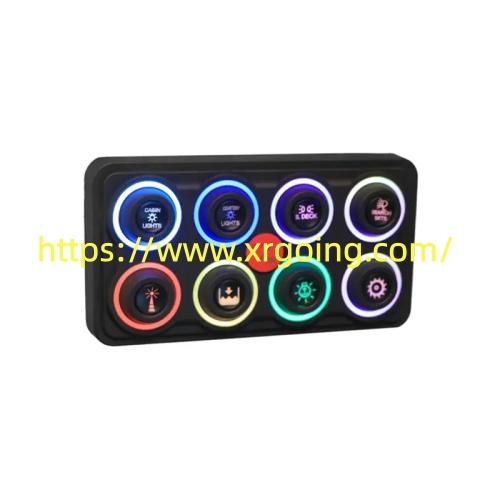
Solenoid Switch units convert a low power electrical signal into controlled mechanical movement through electromagnetic principles. This process begins when current flows through a tightly wound coil of wire. The resulting magnetic field draws a ferromagnetic plunger toward the center of the coil against the force of a return spring. Once the plunger reaches its position it closes or opens a set of heavy duty contacts that complete a high current path. In vehicle starting circuits this action bridges the battery to the starter motor allowing the engine to crank. The same sequence powers fluid control valves conveyor clutches and locking mechanisms on factory floors.
An Electric Solenoid Switch follows identical physics yet is often rated for continuous or intermittent duty depending on the application. In automotive service the device remains energized only during the brief cranking interval. After the engine fires the control circuit drops voltage and the spring returns the plunger to its resting state isolating the motor. Industrial versions may stay energized longer to hold a valve open or keep a machine in a specific position. Duty cycle ratings therefore become a key selection point. Continuous duty coils incorporate thicker wire or heat sinks to manage temperature rise while intermittent designs prioritize rapid response and compact size.
Voltage and current ratings further define suitability. Automotive units commonly operate at twelve or twenty four volts and must handle several hundred amperes at the main contacts. Industrial counterparts appear in both direct current and alternating current forms with coil voltages ranging from twelve to two hundred forty volts. Contact materials such as silver alloys resist arcing and pitting under repeated high load cycles. Housing designs also differ. Vehicle mounted examples use sealed metal cases to withstand road vibration moisture and temperature extremes. Factory mounted versions often feature modular bases for easy panel installation and clear terminal markings.
Proper power delivery ensures consistent actuation. Undersized wiring or corroded terminals create voltage drop that weakens the magnetic field and may leave the plunger only partially engaged. Ground paths must remain clean and low resistance. Many installations place a relay or control module between the ignition key or programmable logic controller and the coil so that the operator switch carries only a small signal current. This arrangement protects both the control interface and the coil windings.
Xiangrui supplies electromagnetic actuators built for these dual environments. The company designs coils contacts and housings that meet the thermal and mechanical demands of road vehicles as well as production equipment.
Maintenance centers on keeping terminals free of oxidation and verifying free plunger travel. Periodic resistance checks of the coil confirm continuity and detect early winding damage. When the unit is removed for service the return spring and contact surfaces receive visual inspection for wear. Reassembly requires correct torque on mounting hardware to avoid housing distortion that could bind the plunger.
Matching the device to the load and duty cycle prevents premature contact erosion and coil overheating. In vehicle applications this means confirming battery health and cable integrity before assuming the unit itself is at fault. On the factory floor it means confirming supply voltage stability and ensuring the controlled load stays within rated limits. When these conditions are observed the electromagnetic actuator delivers repeatable motion year after year.
Product specifications and application notes appear at https://www.xrgoing.com/